
 EN
EN
The Science Behind 1000-Point Accuracy Compensation
Mapping Spatial Nonlinearity Across Wafer and Panel Scales
Achieving micron-level repeatability in chip packaging and PCB drilling demands a dense grid of correction points because spatial errors—driven by thermal gradients, substrate warpage, and guide-way straightness—are inherently nonlinear. On a 300 mm wafer or 600 mm panel, these localized deviations cannot be corrected with a single offset or rigid mechanical shim. A 1000-point compensation map samples the full working envelope, building a software-based error model that dynamically adjusts motion commands across the entire field. Measurements at each node feed into a spline- or polynomial-based interpolation engine, enabling the controller to anticipate and nullify position errors at any coordinate. This approach improves precision by up to 84.3% compared to single-point correction (Keylabs, 2023), while software-driven compensation consistently outperforms static hardware methods (PMC, 2023). By transforming raw encoder feedback into a spatially aware trajectory, the system maintains tool-tip positioning within ±0.5 µm of the ideal path—even under non-homogeneous mechanical deformation.
Vision-Guided Error Calibration and Real-Time Encoder Feedback Integration
To sustain accuracy under dynamic conditions, 4-axis CNC machining and multiaxis servo systems integrate high-resolution vision metrology with nanometer-grade encoder feedback. A grayscale edge-detection camera locates fiducial marks with sub-pixel accuracy, quantifying residual misalignment from thermal drift, clamping distortion, or board stretch. This deviation is streamed into a real-time iterative compensation framework (Hu et al., 2022) that applies axis-specific corrections every servo cycle. Linear encoders with 1 nm resolution—and rotary encoders with 24-bit interpolation—verify that commanded positions are physically achieved, closing the loop at the nanometer level. The fusion of vision-based feed-forward and encoder-based verification cancels both low-frequency geometric errors and high-frequency vibration, converting a conventional 4-axis CNC platform into a self-correcting system. As a result, hole placement tolerances tighten from ±2 µm to ±0.3 µm—even during high-speed drilling—because the controller continuously adapts to actual machine behavior rather than relying on a static kinematic model.
4-Axis CNC Machining: Precision Alignment and Iterative Correction for PCB Drilling
Thermal Expansion, Backlash, and Hole Placement Tolerance Control (±2 µm → ±0.3 µm)
In PCB drilling, ambient temperature fluctuations as small as 5°C can induce 8–12 µm positional shifts via thermal expansion of spindles and ball screws. A 1000-point compensation grid maps these spatial errors across the full panel, feeding real-time corrections directly into the multiaxis servo loop. Backlash—typically 3–5 µm in standard leadscrew systems—is reduced to under 0.5 µm through iterative laser interferometer calibration and bidirectional pitch error mapping. High-resolution linear encoders then suppress remaining thermal and dynamic drift, holding true hole placement to ±0.3 µm: a six-fold improvement over the industry-standard ±2 µm baseline. This level of control is essential for HDI and via-in-pad designs, where a single misplaced microvia can render an entire panel nonfunctional.
Drill Program Compensation with Registration Alignment and XY Stage Dynamics Optimization
Registration alignment begins with vision-based capture of panel fiducials, followed by geometric warping of the drill program to match actual board stretch, skew, and scale distortion. The 1000-point grid model translates each theoretical hole coordinate into a compensated position—accounting for orthogonality errors, local warpage, and nonlinear scaling. Simultaneously, XY stage dynamics are optimized to eliminate overshoot and resonance: S-curve acceleration profiles limit jerk to 30 m/s³, while servo tuning parameters are updated every 200 ms using real-time encoder feedback. This synchronized, multi-layered compensation—from registration mapping to motion control—ensures 0.15 mm microvias land precisely on target and maintains inter-hole tolerances within 5 µm across a full 600 mm panel.
Multiaxis Servo Performance and Closed-Loop Feedback in High-Speed Manufacturing
Motor Selection, Microstepping Resolution, and Signal Integrity in Motion Control
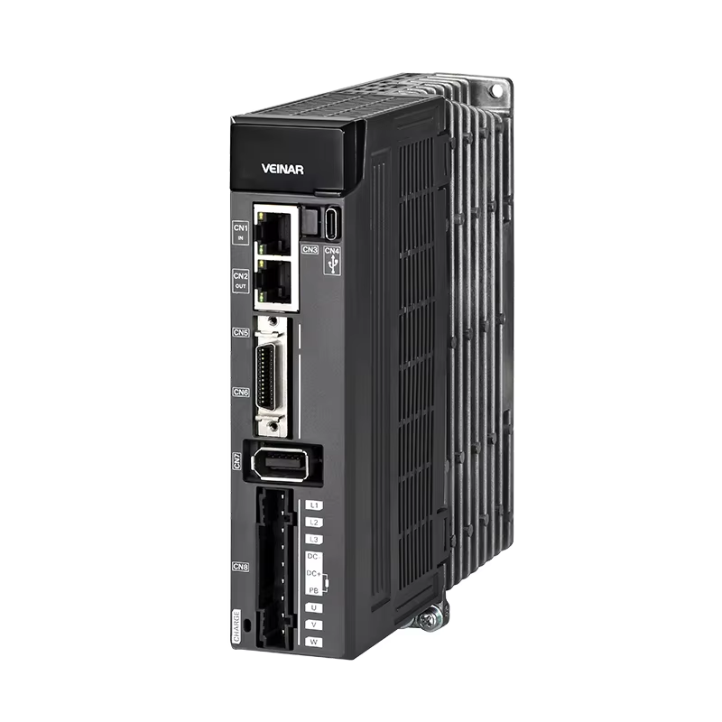
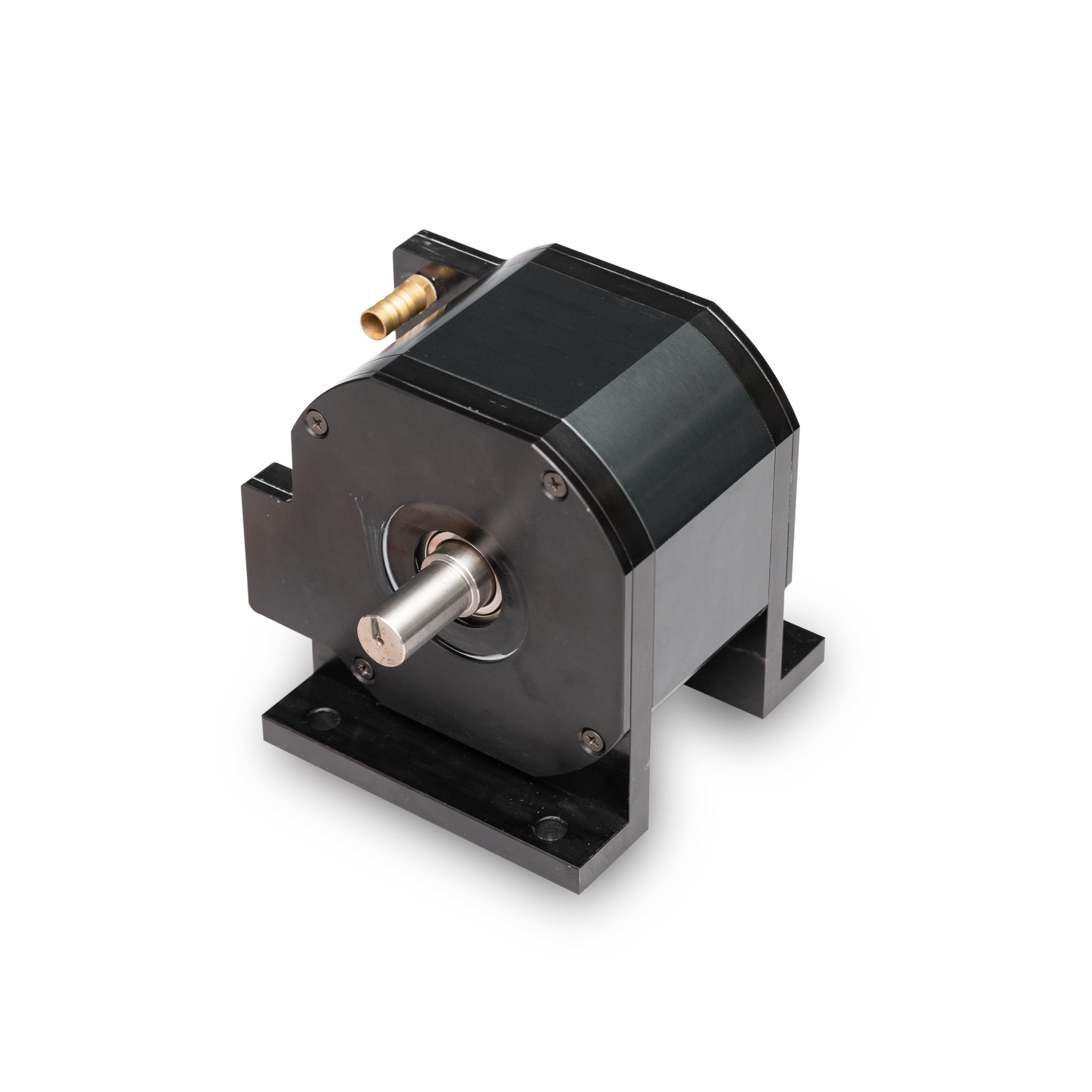
Multiaxis servo motors—not steppers—are foundational to achieving micron-level accuracy in PCB drilling and chip packaging. Unlike open-loop stepper systems, servos deliver consistent torque across speed ranges and prevent step loss during rapid acceleration or under load. A 20-bit encoder provides over 1 million counts per revolution, resolving angular position to 0.00009°; when paired with precise mechanical transmission, this enables sub-micron linear positioning. While microstepping drives can smooth motion, only closed-loop encoder feedback guarantees that the commanded position matches physical reality. Signal integrity is equally critical: electrical noise from drives, motors, or power lines can corrupt encoder data, introducing jitter and positioning errors. Differential signaling (RS-422), shielded twisted-pair cabling, and proper grounding preserve signal fidelity. The servo drive continuously validates encoder health—rejecting faulty readings and maintaining loop stability—so the 1000-point compensation model operates reliably across thousands of cycles.
Sub-Pixel Vision Guidance: Mitigating Lighting Variability and Mechanical Misalignment
Sub-pixel vision guidance enables alignment accuracy beyond native pixel resolution—critical for micron-level targeting in chip packaging and PCB drilling. Lighting variability, such as uneven illumination or specular highlights, can shift perceived feature edges by several microns. To counteract this, vision systems employ uniform coaxial diffuse lighting and adaptive contrast normalization algorithms. Mechanical misalignment—caused by stage backlash, lead screw wear, or thermal expansion—is detected in real time: high-resolution images of fiducials undergo sub-pixel edge detection, generating precise X/Y/Z offsets. These are fed directly into the multiaxis servo controller, which adjusts the tool path within milliseconds. For example, a 0.5 µm thermal drift is identified and compensated before the next drilling cycle begins—preserving the fidelity of the 1000-point compensation map. This closed-loop integration ensures mechanical imperfections never propagate into final placement, making sub-pixel vision a cornerstone of robust, high-speed micron-level manufacturing.
FAQ Section
What is the main purpose of 1000-point accuracy compensation?
The 1000-point accuracy compensation aims to achieve micron-level precision in applications like PCB drilling and chip packaging by mapping spatial errors across an entire working envelope. It uses interpolated software models to dynamically adjust motion commands, ensuring accurate positioning.
How does vision-guided error calibration enhance CNC machining accuracy?
Vision-guided error calibration employs high-resolution cameras to detect fiducial marks and quantify misalignments. These deviations are corrected in real-time using encoder feedback, drastically improving alignment and tool positioning accuracy.
Why are servo motors preferred over stepper motors for high-speed manufacturing?
Servo motors are preferred due to their consistency in torque across speed ranges, closed-loop feedback for precise positioning, and resistance to step loss under load, making them ideal for high-precision tasks.
How does thermal expansion affect PCB drilling accuracy?
Thermal expansion can cause positional shifts of up to 12 µm. Real-time corrections via a 1000-point compensation grid mitigate these errors, ensuring consistent precision even under temperature fluctuations.