

The Core Challenge: Why Gantry Synchronization Directly Governs Volumetric Accuracy
In large-scale machine tools, volumetric accuracy—the ability to position a tool at any point within the work envelope with minimal error—hinges on real-time synchronization between the two gantry axes. Any lag or mismatch between the Y1 and Y2 drives produces dimensional deviations that compound across long travel distances. A high-speed sync multiaxis drive architecture is essential to maintain parallelism under varying cutting loads and thermal conditions.
Racking Error and Structural Compliance: How Asynchronous Motion Induces Geometric Deviation
When gantry axes move out of phase, the crossbeam experiences a racking moment—one end leads while the other lags. This torsional deflection forces the vertical Z-axis to tilt, causing the cutting tool to deviate from its intended path. Even a 10 µm lag between drives can translate into 50+ µm of positional error at the tool tip due to lever arm amplification. Structural compliance of the machine frame further magnifies such errors, especially in slender gantry beams spanning 3–6 meters. Asynchronous motion directly converts electrical misalignment into mechanical distortion, making synchronization fidelity the single largest contributor to geometric deviation in large-format machining.
Thermal Drift and Dynamic Load Effects on Synchronization Stability
Thermal expansion of ball screws and guideways, combined with varying thrust loads during heavy cuts, introduces asymmetric friction that alters each axis’s response. Without closed-loop compensation, a 2 °C temperature difference between Y1 and Y2 can shift synchronization timing by 15–20 µs, leading to differential positioning errors. Dynamic load changes—such as sudden face mill engagement or breakout vibration—further destabilize phase alignment. Advanced controllers monitor motor currents and encoder feedback to counteract these disturbances, but the fundamental requirement remains: the drive system must anticipate and cancel drift before it degrades volumetric accuracy.
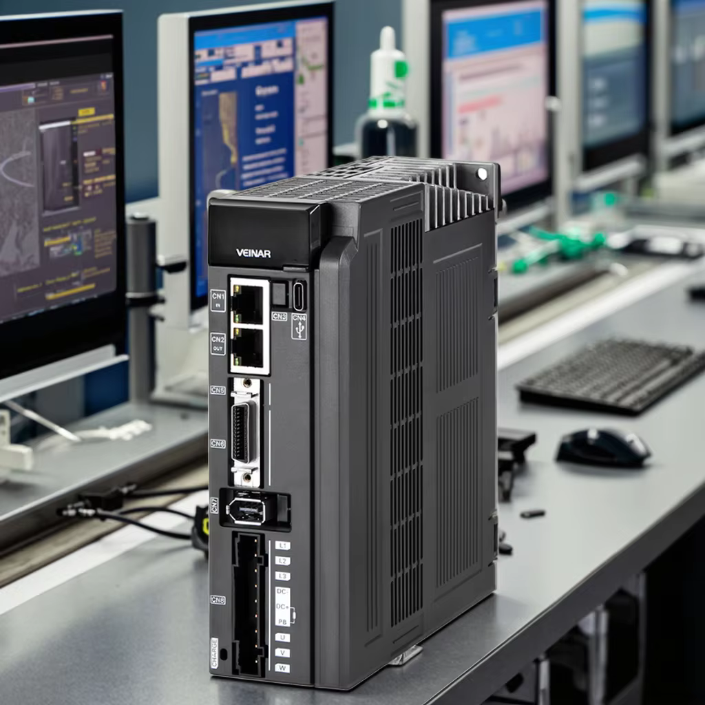
Highspeed Sync Multiaxis Drive Architecture: Enabling Real-Time Axis Coordination
Deterministic Motion Control: EtherCAT-Based Drive Systems with Sub-100 µs Jitter
Achieving sub-100 µs jitter requires a deterministic real-time network. EtherCAT, a high-speed industrial Ethernet protocol, synchronizes multiple servo drives on a common clock cycle. Its distributed clock mechanism ensures that each axis receives position commands and executes feedback loops at precisely the same instant—eliminating cumulative drift. In gantry-type machine tools, where two motors drive a single moving beam, even microsecond-level timing mismatches introduce angular error: a 100 µs offset can cause a 0.02 mm deviation on a 2 m structure. The key performance metric is sync jitter—the variance between actual and commanded execution time. EtherCAT achieves jitter below 100 µs across 16+ axes, and integrated Digital Signal Processing (DSP) in modern servo drives compensates for residual network latency offsets. The result is tightly coordinated left/right gantry motion that supports contouring accuracy compliant with ISO 230‑2 standards for straightness and squareness.
Spindle-Gantry Phase Alignment During High-Feed Contouring
During high-feed contouring, spindle–gantry phase alignment is critical to avoid toolpath distortion. Inertia-induced lag in non-drive axes becomes pronounced during rapid gantry acceleration or deceleration. To counter this, look-ahead algorithms predict required spindle phase shifts relative to the gantry’s actual linear position. If phase mismatch exceeds 0.5°, variable chip loads degrade surface finish. Modern drives use torque feed-forward and cross-axis gain scheduling to adjust current in real time—keeping spindle angular position synchronized to within 1 arc-second of the commanded value. This precision is especially vital during helical interpolation or circular milling: a 10-millisecond offset in the spindle–gantry link can produce a 0.03 mm scallop height error. By locking spindle rotation angle to gantry linear position, machines achieve stable chip evacuation and consistent part tolerances at feed rates up to 10 m/min.
Closed-Loop Synchronization: Feedback Strategies to Compensate for Structural Rigidity Limits
While high-speed sync multiaxis drive architectures provide sub-100 µs axis coordination, structural rigidity limits still induce deflections that must be corrected through feedback. Closed-loop synchronization strategies compare actual axis positions against commanded paths and apply real-time corrections to maintain volumetric accuracy.
Linear Scale vs. Encoder Feedback: Accuracy Trade-offs Under Frame Deflection
Linear scales mounted directly on the machine bed measure table position with sub-micron resolution, offering high absolute accuracy. However, frame deflection can shift the scale relative to the tool point, introducing errors that the feedback loop cannot fully correct. Rotary encoders on the motor shaft are more robust against deflection because they are not physically tied to the bed—but they cannot account for backlash, windup, or structural compliance between motor and load. Under heavy cutting loads, this limitation can result in position errors of several microns. The choice depends on the dominant error source: linear scales excel when bed deformation is minimal and repeatable; encoders are preferred when the mechanical loop is stiff and well-characterized.
Volumetric Error Allocation: Quantifying Y-Axis Synchronization Mismatch as the Dominant Error Source
In large gantry machine tools, the Y-axis typically spans the greatest distance and carries the most mass—making its synchronization accuracy critical. Even a 0.01 mm mismatch between the two Y-axis drives produces a racking error that rotates the gantry, amplifying positioning errors at the spindle tip by a factor proportional to the gantry width. Error budgeting studies consistently show that Y-axis synchronization mismatch accounts for the largest single contribution to overall volumetric error—often exceeding 50% of the total. This dominance means that improving Y-axis feedback and control is the most effective lever for enhancing overall machining accuracy.
Validated Performance: Case Evidence of Synchronization-Driven Accuracy Gains
Real-world implementations of high-speed sync multiaxis drive architecture have demonstrated measurable improvements in volumetric accuracy. In a controlled production trial, a dual-gantry machining center retrofitted with deterministic EtherCAT-based synchronization reduced Y-axis positioning error from ±12 µm to ±2.3 µm under high-feed contouring. The same system achieved a 40% reduction in scrap rate when machining large aluminum aerospace components—parts requiring tight tolerance bands across a 3-meter work envelope. These results confirm that sub-100 µs axis coordination, combined with real-time thermal drift compensation, transforms theoretical alignment limits into consistent, repeatable geometry.
Table of Contents
- The Core Challenge: Why Gantry Synchronization Directly Governs Volumetric Accuracy
- Highspeed Sync Multiaxis Drive Architecture: Enabling Real-Time Axis Coordination
- Closed-Loop Synchronization: Feedback Strategies to Compensate for Structural Rigidity Limits
- Validated Performance: Case Evidence of Synchronization-Driven Accuracy Gains