
 EN
EN
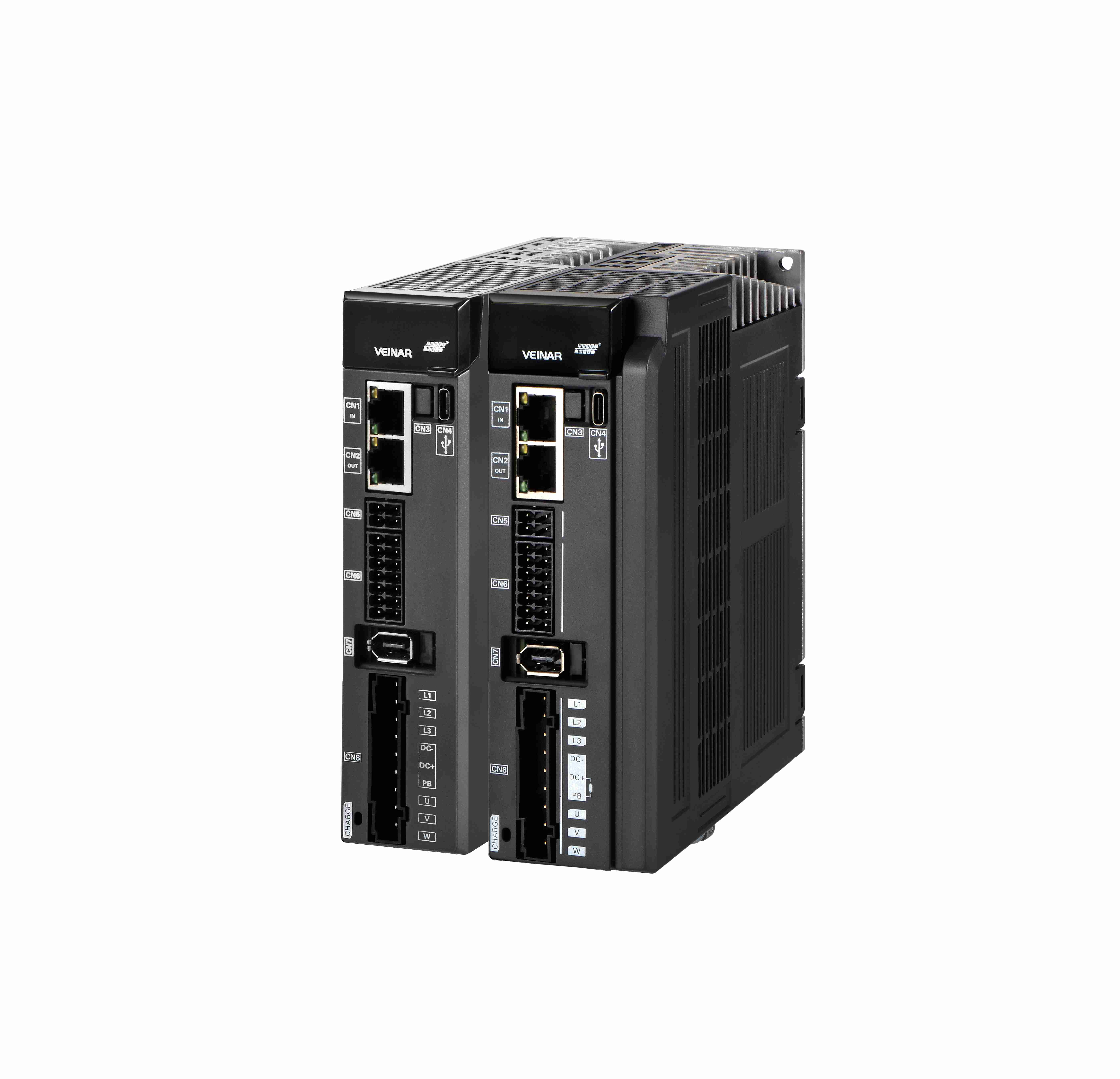
Match Drive Capability to Load Dynamics: Mass, Force, and Duty Cycle
Selecting a voice coil motor driver begins with a rigorous analysis of the load it must move. The driver’s force output must overcome inertia, gravity, and friction across the entire motion profile. A mismatch leads to stalling or an oversized, inefficient system. The key is translating these physical dynamics into a precise force budget—validated at both peak and sustained levels.
Calculating Required Peak and Continuous Force Based on Inertial Load, Gravity, and Friction
Peak force is the sum of inertial, gravitational, and frictional forces. Inertial force dominates in most high-acceleration applications and is calculated using Newton’s second law ($F = ma$), where $m$ is the total moving mass and $a$ is maximum acceleration. Gravitational force equals $mg$ for vertical motion. Friction includes stiction, Coulomb, and viscous components; modeling worst-case values provides a robust estimate. For example, in a vertical pick-and-place application with a 0.5 kg payload accelerating at 5 g ($49\ \text{m/s}^2$), inertial force is $24.5\ \text{N}$, gravitational force is $4.9\ \text{N}$, and estimated friction adds $2\ \text{N}$—yielding a peak force requirement of $31.4\ \text{N}$.
Continuous force—expressed as $F_{RMS}$—is derived from the full force-time profile: square each force value weighted by its duration, average over the cycle, then take the square root. This metric reflects true thermal loading. Specifying only peak force is a common error that leads to thermal failure, as $F_{RMS}$ determines whether the driver stays within its continuous current and temperature limits.
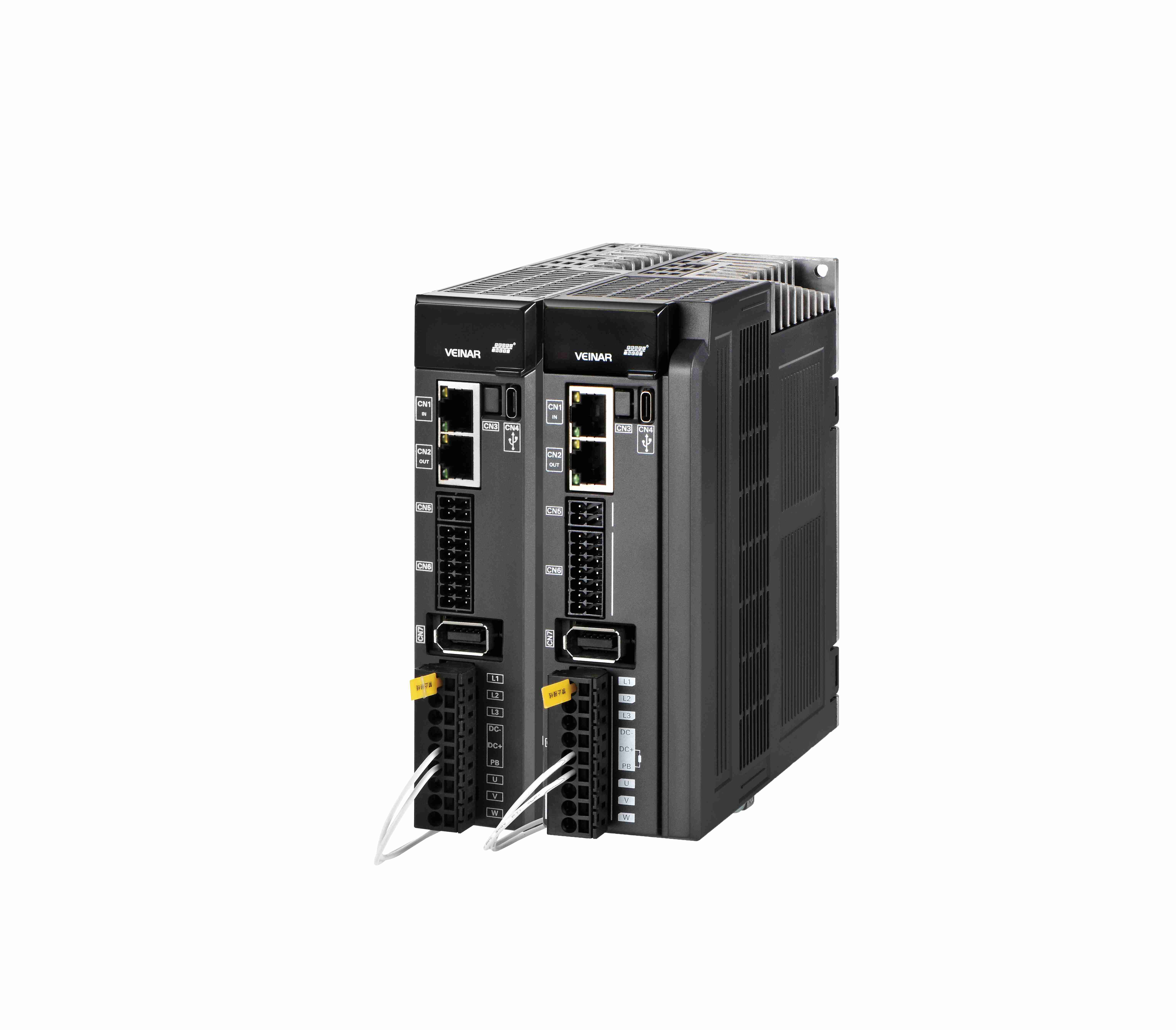
Thermal Management Implications of Duty Cycle and Force Profile Over Time
Voice coil motor drivers are thermally limited by $I^2R$ losses in the coil. The duty cycle—the percentage of time under active load—directly governs average power dissipation. Continuous or high-duty-cycle operation demands superior thermal management; low-duty-cycle applications can often rely on passive cooling. Continuous force ratings are typically specified at 25°C ambient; for every 10°C rise in coil temperature, insulation life may halve. Field failures linked to thermal stress cost industry an estimated $3.2 billion annually in downtime (Ponemon Institute, 2023).
| Thermal Management Class | Typical Heat Dissipation Method | Duty Cycle Suitability | Risk Profile |
|---|---|---|---|
| Class 1: Passive | Natural convection and radiation | Low (<10%) | High risk of thermal runaway if duty cycle is exceeded. |
| Class 2: Active | Forced-air cooling or heat sinking | Medium (10–60%) | Performance depends heavily on ambient temperature and airflow consistency. |
| Class 3: High-Performance | Liquid cooling or integrated Peltier module | Continuous (100%) | Requires complex integration and maintenance but enables sustained high-force operation. |
An active vibration isolation system requiring constant force needs Class 3. In contrast, a semiconductor wafer handler with high peak force but only a 5% duty cycle may safely use Class 1—if the $F_{RMS}$ calculation confirms adequate thermal margin. Ignoring the correlation between force-time integral and thermal resistance remains a leading cause of field failure.
Ensure Control Precision with Compatible Feedback and Closed-Loop Stability
A voice coil motor’s linear force output delivers real-world precision only when tightly coupled to high-fidelity feedback and a stable, low-latency control loop. Sensor choice and loop tuning determine position hold, disturbance rejection, and trajectory tracking fidelity.
Encoder Resolution vs. Hall Sensor Limits for Sub-Micron Positioning Accuracy
Hall sensors offer robustness and low cost but are typically limited to 1–5 µm resolution due to magnetic field granularity and signal-to-noise constraints. Optical linear encoders with nanometer-scale interpolation achieve resolutions down to 0.1 nm—enabling true sub-micron positioning. Replacing Hall feedback with such encoders routinely improves static accuracy by one to two orders of magnitude. For applications requiring features below 1 µm—like semiconductor inspection or laser micro-machining—subdivision error and cyclic error become critical: non-linearities in the encoder scale introduce periodic jitter that degrades stability. Choose a driver supporting high-speed digital interfaces (e.g., BiSS-C or EnDat 2.2) to preserve native sensor resolution without quantization loss.
Bandwidth, Phase Margin, and Latency Trade-offs in Voice Coil Motor Driver Control Loops
Sub-micron stability requires more than resolution—it demands minimal latency and sufficient phase margin. While current-loop bandwidths commonly reach 5–10 kHz, outer position-loop bandwidth is constrained by mechanical resonance, often falling between 200 Hz and 1 kHz. Every microsecond of transport delay—from sensor sampling through filtering to PWM update—erodes phase margin, forcing conservative gain settings and reducing stiffness. A well-tuned driver with <2 µs latency and 45°–60° phase margin can suppress 100 Hz disturbances by 40 dB; increasing latency to 10 µs cuts that attenuation in half. Co-designing the feedback filter, current-loop PI parameters, and velocity observer is essential to avoid exciting mechanical resonances.
Verify Voice Coil Motor Driver Compatibility: Kt, Ke, and Current Compliance
Why Kt–Ke Consistency Is Critical for Force Linearity and Thermal Derating in Voice Coil Motor Drivers
Kt (force constant) and Ke (back EMF constant) are fundamentally linked by electromagnetic design. Consistency between them ensures force linearity: any mismatch causes actual force to deviate from commanded current, introducing positioning errors that degrade sub-micron accuracy. A 2019 study found that a 10% Kt variation produced 12% force non-linearity. Thermal derating also hinges on accurate Kt values—if Kt drops with temperature, the driver must increase current to maintain force, raising heat and risking current compliance violations. Kt–Ke inconsistency thus undermines overcurrent protection and thermal safety. Engineers should verify Kt–Ke alignment under worst-case thermal conditions before finalizing selection.
Optimize System Bandwidth: Amplifier Slew Rate, Sensor Update, and Mechanical Resonance
System bandwidth is governed by three interdependent limits: amplifier slew rate, sensor update rate, and mechanical resonance frequency.
Slew rate defines how quickly the driver can change output current. If required $dI/dt$ exceeds the amplifier’s capability, lag and distortion reduce closed-loop bandwidth. As a rule, select a driver whose slew rate exceeds the maximum expected $dI/dt$ by at least 3×—especially for high-acceleration moves.
Sensor update rate introduces a discrete-time bottleneck. To avoid aliasing and destabilizing phase lag, sample position feedback at 10–20× the target control bandwidth. For instance, a 1 kHz encoder update rate effectively caps usable bandwidth at ~50–100 Hz.
Finally, mechanical resonance—the natural frequency of the coil-load-flexure system—imposes a hard ceiling. Unity-gain crossover must be kept at least 3–5× below the first resonance. Exceeding this risks oscillation due to rapid phase loss. Always verify structural resonance via frequency sweep during integration.
Avoid Common Selection Pitfalls: Real-World Validation Checklist for Voice Coil Motor Drivers
Integrating a voice coil motor driver can fail catastrophically if validation skips real-world dynamics. Static specs alone mask weaknesses in thermal response, force fidelity, and loop stability. A structured checklist prevents costly re-spins and field failures.
Pre-Integration Testing: Simulated Load Profiles and Thermal Soak Validation
Before committing, subject the driver to a representative load map reflecting worst-case inertial, gravitational, and frictional forces. Internal data from a leading manufacturer shows that 22% of driver failures in high-cycle applications stemmed from underestimating peak-to-continuous force ratios during rapid acceleration.
Run a thermal soak test at maximum rated ambient temperature while delivering the RMS current profile. Measure winding temperature rise using embedded thermistors and log internal driver temperature sensors. If enclosure design restricts heat dissipation, extend the soak to 2–3 hours to reach thermal equilibrium. Any thermal throttling or unexpected current foldback indicates inadequate thermal design for the actual duty cycle—not just datasheet averages.
Vendor Documentation Red Flags: Missing Kt Tolerance, Unspecified Latency, or Omitted Thermal Derating Curves
Scrutinize the datasheet before trusting a driver for closed-loop positioning. A missing Kt tolerance is a critical gap: even ±5% variation can cause force linearity errors exceeding 50 µm in a 200 mm/s move (2023 Motion Control Survey). Unspecified control-loop latency—including ADC conversion, filter delays, and communication overhead—leads to unquantified phase loss that destabilizes high-bandwidth loops. Reputable suppliers provide either a Bode plot or a consolidated latency figure.
Equally concerning is the absence of a thermal derating curve. Without it, predicting current limit reduction at elevated temperatures is impossible—risking silent torque roll-off. Demand three items:
- A Kt vs. rotor position tolerance chart,
- A latency specification broken down by subsystem (ADC, filter, PWM, etc.), and
- A continuous current derating curve across the full operating temperature range.
If any are withheld, treat the driver as a developmental prototype—not a production-ready component.
FAQ
What is the importance of peak and continuous force calculation?
Peak force calculation ensures the driver can meet immediate acceleration demands, whereas continuous force is tied to thermal stability over sustained operation, preventing overheating and thermal failures.
How does the duty cycle affect thermal management?
Higher duty cycles increase power dissipation and necessitate advanced thermal management, such as forced-air or liquid cooling, to prevent thermal runaway.
Why are high-fidelity feedback and low-latency control loops critical for precision?
High-fidelity feedback ensures precise position measurement, while low-latency control loops maintain stability and suppress disturbances in sub-micron applications.
What does Kt–Ke consistency ensure?
It ensures accurate force linearity and thermal behavior, preventing positioning errors and force deviations during operation.
What should be verified in a driver’s datasheet before selection?
Key specifications include Kt tolerance, control-loop latency, and thermal derating curves to ensure reliable long-term performance under worst-case conditions.
Table of Contents
- Match Drive Capability to Load Dynamics: Mass, Force, and Duty Cycle
- Ensure Control Precision with Compatible Feedback and Closed-Loop Stability
- Verify Voice Coil Motor Driver Compatibility: Kt, Ke, and Current Compliance
- Optimize System Bandwidth: Amplifier Slew Rate, Sensor Update, and Mechanical Resonance
- Avoid Common Selection Pitfalls: Real-World Validation Checklist for Voice Coil Motor Drivers
-
FAQ
- What is the importance of peak and continuous force calculation?
- How does the duty cycle affect thermal management?
- Why are high-fidelity feedback and low-latency control loops critical for precision?
- What does Kt–Ke consistency ensure?
- What should be verified in a driver’s datasheet before selection?